Nuclear Diagnostic Experiments and Calibrations
A Proposal Submitted to the Lawrence Livermore National Laboratory by Stephen Padalino of the Nuclear Physics Laboratory At the State University of New York Geneseo, New York May 11, 1999. For the period June 1, 1999 to June 1, 2001 LLNL Collaborator: Craig Sangster
Purpose
The purpose for this proposal is to establish an ongoing collaborative effort between our research group and LLNL scientists and to perform ICF research at Livermore on a regular basis. In order to support this collaboration we are requesting funds for travel, lodging and student stipends. It should be noted that no indirect or overhead costs are associated with this grant and that the full funded amount will be used directly for the project.
Introduction
During the past year faculty and students at the Nuclear Physics Laboratory, (NPL) at the State University of New York in Geneseo, worked with collaborators at LLNL and LLE to develop nuclear diagnostic measurements and calibrations at Omega and NPL. Below is a list of a few of these projects, which are currently underway.
- Tertiary neutron yield measurements using carbon activation
SUNY/Geneseo: Stephen Padalino, Heather Oliver and Joel Nyquis
LLE Collaborators: Stan Skupsky, Vladimir Smalyuk, and Rahda Bahukutumbi
LLNL Collaborator: Craig Sangster
- CPS Burn Time Evolution Detector
SUNY/Geneseo: Stephen Padalino, Kurt Fletcher, Sarah Thompson and Brook Schwartze
LLE-MIT Collaborators: John Soures, Richard Petrasso, Chuck Sorce, and Sam Roberts
LLNL Collaborator: Craig Sangster
- MEDUSA neutron detector elements calibrations ( DD neutrons)
SUNY/Geneseo: Stephen Padalino, Heather Oliver and Joel Nyquist
LLE Collaborators: Vladimir Smalyuk
LLNL Collaborator: Craig Sangster
It is further proposed to perform additional measurements at LLNL and LBNL and advance the work of carbon activation and MEDUSA detector calibrations.
- Calibration measurement of carbon at RTNS LBNL
SUNY/Geneseo: Stephen Padalino, Heather Oliver and Joel Nyquist
LLNL Collaborator: Craig Sangster
- MEDUSA neutron detector elements calibrations ( DT neutrons)
SUNY/Geneseo: Stephen Padalino, Heather Oliver and Joel Nyquist
LLE Collaborators: Vladimir Smalyuk
LLNL Collaborator: Craig Sangster
Tertiary neutron yield measurements using carbon activation
SUNY/Geneseo: Stephen Padalino, Heather Oliver and Joel Nyquist
LLE Collaborators: Stan Skupsky, Vladimir Smalyuk, and Rahda Bahukutumbi
LLNL Collaborators: Craig Sangster

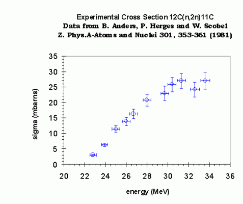
Tertiary neutron yield (TNY) measurements, given their obvious sensitivity to (r r) 2, are of great interest to the theorists. TNY measurements have been attempted on LLE shots that had primary DT neutron yields in excess of 10 13 neutrons, with densities great enough to produce tertiary neutrons. Measurements done by our group thus far at LLE using carbon activation has produced inconclusive results and further work needs to be performed. Even though the experimental method is straightforward it is difficult to analyze the data in practice. During an ICF reaction, 14.1 MeV neutrons emitted from the T(d,n) fusion reaction strike fuel deuterons causing them to accelerate. These deuterons (or tritons) then collide with tritium (or deuterium) respectively, to produce tertiary T(d,n) reactions that emit high energy neutrons in the range of 18 to 30 MeV. A pure carbon sample is placed near the reaction where it becomes activated through the 12C(n,2n) 11C reaction which has a high neutron threshold (around 22 MeV shown below) and can not be activated by the primary neutrons. The 11C consequently beta decays by emitting positrons. Once activated, the sample is removed from the reaction area. NaI detectors are then used to count, in coincidence, the back to back 511 keV gamma rays emitted from the positron annihilation. The number of gamma rays counted is directly related to the tertiary neutron yield of the fusion reaction.
The chief concern of using this method arises from contamination of the graphite with materials that will be activated by the primary 14 MeV neutrons via the (n,2n) reaction. Since there are 10 7 more primaries than tertiaries produced during the burn any contaminant, even at a level of 1 PPM, that produces radioactive products that emit positrons can severely complicate the analysis of the decay curve for 11C. Stable nuclei such as copper, nitrogen and oxygen become activated and then emit positrons thus convoluting the decay spectrum. Many of these contaminants have been investigated through the use of trace elemental analysis at the Cornell Research reactor. Reactor measurements at Cornell showed that high purity graphite obtainable from Bay Graphite Corporation is acceptable for TNY measurements via neutron activation. Many contaminants were identified in the graphite, such as Vanadium.

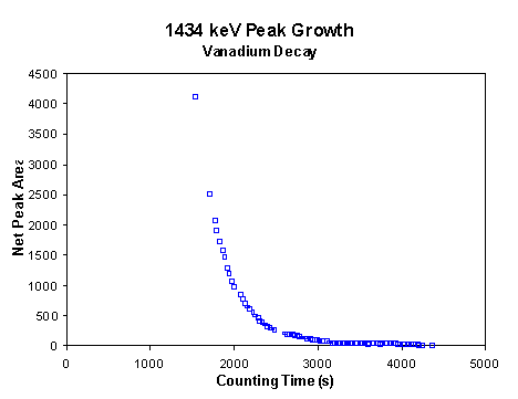
After a 2 hour thermal neutron activation of the graphite sample, in the Cornell research reactor, the above decay curve was measured by detecting 1434 keV gamma rays emitted from the decay of Vanadium. Vanadium is found in this sample at levels of less than 1 PPM but greater than .01 PPM. This would be an unacceptable level if Vanadium was a positron emitter however, given that its half life is long and it is an electron instead of positron emitter it does not pose a counting problem when compared to the short lived 11C positron decay. There are other contaminants which are positrons emitters and have half-lives of the same order as 11C. These do present a problem!
Recent measurements performed at LLE produced interesting results, which require further study. A high purity graphite disk that was covered in plastic to reduce external-surface contamination was activated with a shot that had a primary D-T yield of 10 13 neutrons. The resulting decay spectrum was obtained for the carbon.
To fit the data a double exponential growth curve was required. The sum of the carbon and nitrogen growth curves used the appropriate decay constants based on the 9.97 min half-life for 13N and the 20.39 min half-life for 11C. The nitrogen component was greater than the carbon contribution by at least a factor of 2. This demonstrated that, after background subtraction, approximately 25 +/- 3 counts of the 35 counts measured in 3000 seconds were produced from 13N. Nitrogen – 13 can be produced via the 14N(n,2n) 13N reaction (9 mB @ 14 MeV) but was most likely produced by the 12C(p,gamma) 13N reaction which has a cross-section of ~2.5 barns at 14 MeV. It is believed that recoil protons from elastically scattered 14 MeV neutrons in the shrink-wrap produce fast protons via the p(n,p) reaction. Protons with energies less than or equal to 14 MeV then penetrate the carbon producing 12C(p,gamma) 13N reactions. Nitrogen –13 has a 9.97 min half-life thus dramatically effecting the growth curve for carbon-11 which has a 20.39 min half-life.
A table of possible reactions, which can interfere with this method, is given below. A second attempts to protect the carbon from external-surface contamination also met with failure. Silicon Carbide was used to seal the graphite sample during manufacture. The sample was also placed in shrink-wrap. The combination of shrink-wrap and Silicon produced other nuclear reaction to occur that ultimately generated positrons. These reactions can be seen in the table below.
| Reaction | X-sec | Energy range | Half Life |
| C12(n,2n)C11 | 5-30 mb | 22-35 MeV | 20.3 min |
| C12(p,G)N13 | 2-2.7 b | 5-15 MeV | 9.9 min |
| N14(n,2n)N13 | 9 mb | 14 MeV | 9.9 min |
| Cu63(n,2n)Cu62 | 400 mb | 14 MeV | 9.7 min |
| Si30((p,n)P30 | ? | 2.5 min | |
| Si29(p,G)P30 | ? | 2.5 min | |
| O16(n,2n)O15 | 1.5 mb | 17 MeV | 2.01 min |
| N14(p,G)O15 | ? | 2.01 min |
It is proposed that further studies be performed at the RTNS to determine the best manner of protecting the carbon samples from external-surface contamination with out introducing (p,n) reactions in the carbon.
CPS Burn Time Evolution Detector
SUNY/Geneseo: Stephen Padalino, Kurt Fletcher, Sarah Thompson and Brook Schwarze
LLE-MIT Collaborators: John Soures, Richard Petrasso, Chuck Sorce, and Sam Roberts
LLNL Collaborators: Craig Sangster

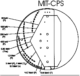
It is proposed that a Burn Time Evolution (BTE) detector be built for the Charged Particle Spectrometer (CPS). The purpose of the BTE would be to count the number of knock on particles emitted as a function of time during the burn. The entire counting process would occur between 500 and 3000 pico-sec.
One design being considered uses PIN diode detectors similar to the setup used on the petawatt laser at Livermore.

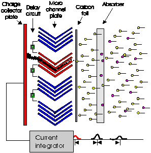
A second possible detector design and electronics setup is shown below. The BTE would be mounted on one of the fingers in the existing CPS. The detector would be constructed of a carbon foil, which would produce electrons when struck by knock on fuel nuclei. A micro-channel plate would amplify the ejected electrons and the resulting electron cascade would be collected by a plate or plates at the back of the detector and amplified with a fast preamp or fast preamp array. The signal would then be recorded with a fast multi channel oscilloscope. This system is analogous to a framing camera. But would detect charged particles instead of x-rays.
MEDUSA neutron detector elements calibrations (DD-neutrons)
Stephen Padalino, Heather Oliver and Joel Nyquist
LLE Collaborators: Vladimir Smalyuk
LLNL Collaborators: Craig Sangster
Over the past year several projects have been initiated using the SUNY Geneseo 2 MV Van de Graaff accelerator to answer key questions related to the Charged Particle Spectrometer (CPS). We propose to continue and expand these efforts in the coming 12 months. These efforts also coincide with our desire to build and test a CPS Burn Time Evolution Detector.
Proof-of-Principle

For over six months members of our group have been performing tests on the CR39 track detectors used in the CPS to determine the effects of particle energy, particle type, and other factors on the track diameters. This work was led by J. Law of LLE, and in recent months, C. Sorce and S. Roberts of LLE. These tests involved using elastic scattering of protons from gold targets at back angles, a technique known as Rutherford Backscattering (RBS). The CR39 samples and an active 100 mm surface barrier detector were each placed at 135° on opposite sides of the scattering chamber. The energy and particle flux of protons was determined using the calibrated surface barrier detector, and the track diameters were measured at LLE. Some results are shown in Figure 1.
Figure 1. Track Diameter in CR39 vs. proton energy. The protons where produced at the Geneseo accelerator lab.
In addition to these RBS tests, we are able to produce high energy protons via nuclear fusion reactions in order to refine the detection system for the CPS. For many years we have been using the D(d,n) 3He reaction to characterize neutron detectors, and we can easily produce 2.4 to 5.2 MeV protons using the D(d,p) 3H reaction. In addition, tritons and 3He ions are produced. For these experiments, we use transmission-type, deuterated polyethylene targets fabricated at the Geneseo Thin Films Laboratory. Similarly, this summer we have shown that we can initiate 3He(d,p) 4He reaction to produce protons with energies of about 13.3 to 17.0 MeV. For these experiments, we used targets which are tantalum foils with 3He implanted at low energies (20 keV), fabricated at Triangle Universities Nuclear Lab (TUNL) in Durham, NC [Gei96]. These targets stop the 450-keV deuterons. Figure 2 shows spectra for the d- 3He tests. The target thickness was determined to be 1.5 ´10 16 3He/cm 2. To obtain these spectra, the 1500- mm surface barrier detector with a solid angle of 2.38 mSr was placed at 135 ° and a 1.5- mA deuteron beam was used to obtain a count rate of 25 protons/sec. The second figure shows the result of an earlier test when a 39.6-mil aluminum plate is rotated in front of the detector, and the 13.8 MeV protons are ranged down to an energy of 3.3 MeV. These figures demonstrate our ability to produce high energy protons for ranging experiments.


Figure 2. 3He(d,p) 4He at Geneseo. In the top figure, the 13.8 MeV protons are stopped in the 1500 mm surface barrier detector covered with a 0.25 mil mylar foil to eliminate elastically scattered deuterons. The low energy peaks (at 1.7 and 2.5 MeV) are believed to be d- 3He alphas (1.7 MeV) which pass through the mylar and protons (2.5 MeV) from D(d,p) 3H from deuterium implanted in the target by the beam. In the bottom figure, a 39.6 mil Aluminum plate was positioned in front of the detector, shifting the protons to about 3.3 MeV. (The amplifier gains were set differently for the two runs.)
Because the CR39 is relatively insensitive to high energy charged particles, the detection system for the CPS requires filters to range down the energies of the particles. Using the Geneseo accelerator, we can determine the average energy and energy distribution through various filters experimentally. This work is rather critical; for example, if the 13.8 MeV protons emitted via 3He(d,p) 4He at 135° pass through a 40-mil aluminum plate, the exit energy is 2.9 MeV. If the plate is 39.5 mils, the exit energy is 3.2 MeV. For this example, a 1% variation in the filter thickness produces a 10% effect on the exiting energy, and this situation gets worse the further one degrades the energy. A compilation of charged particles and available energies at Geneseo is provided in Table 1.
| RBS | D(d,p)3H | D(d,n)3He | 3He(d,p)4He | 12C(d,p)13C | ||
| Protons | 0.1 – 1.6 | 2.4 – 5.2 | ———- | 13.3 – 17.0 | 3.0 – 3.8 | |
| Deuterons | 0.1 – 1.6 | (0.2 – 1.6) | (0.2 – 1.6) | (0.2 – 0.6) | (0.8 – 1.2) | |
| Tritons | ———- | 0.6 – 2.7 | ———- | ———- | ———- | |
| Helium-3 | possible | ———- | 0.6 – 1.3 | ———- | ———- | |
| Helium-4 | possible | ———- | ———- | 2.0 – 6.7 | ———- |
However, performing these tests may require improvements in our targets. While the procedures for making deuterated targets are in good shape, thicker 3He targets are needed to produce good statistics in a reasonable counting time. Our existing 3He target has become depleted over time, and a factor of ten improvement in target thickness is possible using the fabrication method mentioned above. This will require the use of a General Ionex 1080 Focussed Ion Beam Sputtering System, such as the one at TUNL. As an alternative, a 3He gas cell system can be used, although the use of entrance foils requires higher energy deuteron beams. Both of these targetry methods will be investigated during the next funding period.
References
[Gei69] “Ion Implanted 3He Targets for Very Low Energy Experiments,” W. Geist, Z. Ayer, A.C. Hird, E.J. Ludwig, M. Wood, and K.A. Fletcher, Nuclear Instruments and Methods B 111 (1996) 176-180.
